Residential Plan Review Requirements
The following is a list of the items required on residential plans for the North Carolina Residential Code 2018 Edition, based on the International Residential Code.
*All notated below must be shown on plans.
Note: Need to submit plans as built on site, we do NOT accept reversed plans.
- Engineer, Architect or Designer must reference that plans are designed to meet the requirements of the North Carolina Residential Code 2018 Edition
- House elevations – Front, Rear and Side *Exterior wall coverings (i.e. Brick, Vinyl, Stucco, Hard Board, Stone, Lap Siding) Chapter 7
- Design Criteria – Section R301 Buildings and Structures shall be constructed to safely support all loads as outlined
- Slab, footing, and pier – Show width and depth including all dimensions and spacing requirements. Chapter 4, Section R403
- Specific foundation wall detailing – Type of materials width and height. *Basement-Max wall height, max backfill and type of backfill, pre-engineered wall system with soil bearing certification. Chapter 4, Section R 404
- Foundation: Closed crawlspaces per R409/Wall vented crawl spaces R408: (1) Foundation vent calculations and location (2) Drain locations (3) Ground cover
- Anchor bolts for foundation must be noted. Section R403
- Floor system – Girder sizes and locations, floor joist direction, size, species, span, spacing, details and cripple wall details and cantilevers. (Engineered floor system must include point loads and specifications from the wood products engineers. All design must be submitted and approved through the plan review process prior to construction.) Chapter 5
- Cantilevers and exterior. Chapter 5
- All deck details including cantilevers must be shown on plans. (See Appendix M)
- Floor plan – Location and size of walls, windows, doors, stairs, headers, include spans and supports (stud columns) with number of jack/king studs and attachments
- Wall bracing: buildings and portions there of shall be braced in accordance with one or more of the following sections using bracing materials and methods complying with Section R602.10.1 and all load path detailing in accordance with section R602.10.4 details must be specified on plans.
- Roof ceiling – Ceiling joist and rafters direction, size, species, span and spacing. Show ridge size support and all details of vaults, cathedral, valley supports and roof vent calculations. Ceiling joist and rafter connections shall be made in accordance with R802 *note attic access Section R807
- Truss layouts must illustrate bearing walls and load points greater than 3,000 lbs. with appropriate stud columns through the structure. Truss design drawings shall be prepared in accordance with section R802.10 and be provided for approval at plan review. *Sealed by professional engineer
- Show cross-sections of interior and exterior walls.
- Chimneys or fireplaces with details (vented or non-vented). Chapter 10
- All energy details must be submitted on plans!
- Energy Compliance: (Per Chapter 4)
- Window U-factor and design pressure
- Glazing area
- Climate zone
- Type, thickness, R value of insulation
- Energy Compliance: (Per Chapter 4)
- Need to identify all rooms. (With specific name of each room use)
- Note: All load points must show path of travel to earth through all floor plans stud columns with number of bearing studs or other approved support structure(s).
- RESIDENTIAL WALL BRACING PLAN REVIEW CHECKLIST
- Plans must reference the 2018 NCRC. Every plan requires the following. (It is recommended that a separate wall bracing sheet be provided.)
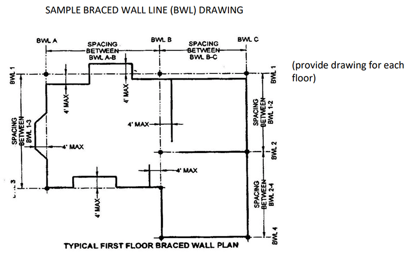
- Identify each braced wall line (BWL) for each floor (see example below)
- Identify each braced wall method utilized for each BWL (i.e. LIB, GB, DWB, WSP, SFB, PBS, PCH, HPS, CS, etc.)
- Provide the nailing pattern for each brace wall method specified.
- Identify the minimum required length of brace wall panels for each BWL.
- Identify the provided length of braced wall panels for each BWL.
- Specific location of braced wall panels (dimension the length on the plan)
- Identify the location and the type of hold downs NOTE: Alternate methods must include all of the above and should spec note the prescriptive requirements they are equal to.
- Provide these details on the plan if applicable. i. Hold down details.
- Required footing connections noted on the Footing/Foundation sheet.
- Masonry stem wall details (see NCRC Figure R602.10.7 as an example of the prescriptive requirements.)
- Wall to floor/ceiling framing connection details
- Wall to rafter/truss faming connection details
- Portal framing details vii. Other necessary details SAMPLE BRACED WALL LINE (BWL) DRAWING (provide drawing for each floor)

REVISED: JANUARY 3, 2019